THOR is a two-phase, non-equilibrium, fluid dynamics model for flow networks. CORYS offers THOR to the simulation industry for modeling complex, multi-phase fluid systems with high fidelity results.
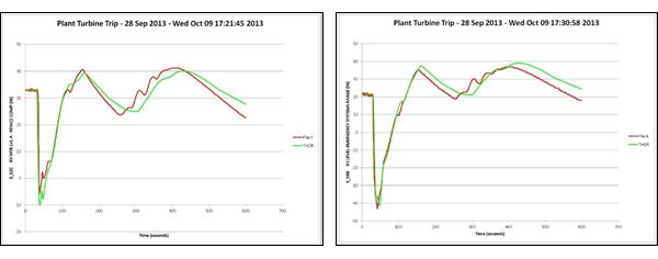
THOR is installed on more nuclear power plant simulators than any other advanced thermal hydraulics model. The THOR models have been benchmarked extensively through more than 80 installations world-wide. The fidelity and robustness of the THOR models is well-established. Below are comparisons between THOR simulation models and actual plant data for a turbine trip event at Browns Ferry Nuclear Station.
The THOR model is capable of simulating the flow of water, steam, multiple non-condensable gases, and any mixture of those fluids. The non-condensable gases may be soluble in the water. Both the liquid and the gas phase may contain, and transport, trace components that do not interact thermodynamically with the fluids. The steam tables extend to the critical pressure; the equation of state for the noncondensable gases is the perfect gas law. Chemical reaction between the non-condensable gases is permitted.
In addition to the basic solution of the fluid dynamics for flow networks, the THOR contains a number of specialized models, which are executed as an integral part of the simulation. The models are for:
Valves and check valves
Centrifugal pumps and blowers
Constant displacement pumps
Compressors
Combustors
Gas turbines
Steam turbines
Heat exchangers, including condensers and boilers
Heat loss to walls
Filters and condensate polishers
Desiccanters
Recombiners
Demineralizers
Steam jet air ejectors
Water level instrumentation
The system is divided into control volumes (cells) and conduits (flowpaths). The flowpaths connect the cells. Conservation equations for one-dimensional flow for the mass of steam, water, non-condensable gasses, trace components, and energy for the gaseous and liquid components, are integrated for all the cells. The flows in flowpaths are computed from the transient momentum equation for the fluid mixture. For two-phase systems, the relative velocity between the phases is evaluated from the drift flux model.
The model uses best-estimate constitutive relationships for heat transfer, phase-change, drift flux, choked mass flow rates for steam/water, and solubility of non-condensable gasses. Because of the completeness of the equations of state, constitutive relationships, and conservation equations, the model can be used to simulate most practical problems of fluid dynamics, including compressible gas dynamics involving wave phenomena, choking, and combustion. Natural convective currents, driven by temperature differences, are inherent in the model. However, for connections to dead-end compartment special care must be taken to ensure that proper exchange of mass and energy and mass can take place. This can be accomplished both by extra flowpaths with properly imposed flow, and by specifying diffusion of heat and trace element between cells.
For nuclear reactors the simulator thermal hydraulics models are valid as long the external geometry of the reactor core remains intact. The effects of ballooning and disintegrating fuel rods are not considered. The application of the model is appropriate for all fluid systems typically found in the power generation industry. This includes the nuclear steam supply systems, balance of plant systems, support systems, and heating and ventilation systems for nuclear power plants as well as fuel systems, gas turbines, and steam systems for non-nuclear power generation plants.
Cells are control volumes for which the conservation equations are integrated. The conservation equations are for mass of the individual fluids, trace components, and energy for the liquid and gas phases. Cells may be grouped together in a “regions.” A region is a collection of cells for which the “region pressure” is used to evaluate the fluid densities of the cells belonging to the region. The region pressure computed such that all the conservation equations are satisfied. Most regions consist of just one cell, but the multi-cell region capability may be used with advantage in some situations.
Cells may be connected with flowpaths, which are conduits for mass and energy flow of the fluids and trace components. The volumetric flow rate for the fluid mixture in a flowpath is evaluated from the transient momentum equation. The phasic flow rates for the liquid and gas phases are obtained by applying the drift flux model. The mass and energy flow rates by using a donor cell approach.
A unique and critical feature of THOR is the numerical solution. The numerical integration method in THOR is explicit Euler. At each time step, this linear integration method integrates the conservation equations one by one. It offers the lowest possible computer time per time step. In addition, the conservation equations for mass and energy are written in conserving form, thus guaranteeing exact system-wide conservation of mass and energy.
The chief advantages of the THOR explicit method of integration are the simplicity of the code, the short execution time per time step, and the fact that the execution time is proportional to the number of control volumes in the simulated system.
(Most simulators use implicit integration methods for which the integration time is longer per time step, and, at best, proportional the square of the number of control volumes.)
To maintain numerical stability, the explicit method requires smaller time steps than implicit methods. But because of the faster execution time per time step this is not a drawback. The short integration time step, required for numerical stability, has the advantage of reducing the numerical integration error, which is proportional to the time step.
Because some sub-systems may require very short time steps for numerical stability (small cells connected with wide flow paths), the THOR code has the ability to execute these sub-systems at a high iteration rate. Thus, for example, if the system wide iteration rate is 100 cps, certain sub-system may be integrated at 200 or even higher rates. This feature saves computer power by avoiding having to integrate the whole system at the higher rate.
The following field equations apply to THOR:
Gas mass conservation equation
Liquid mass conservation equation
Gas energy conservation equation
Liquid energy conservation equation
Mixture momentum equation
Mass conservation equations for gaseous non-condensable gasses
Mass conservation equations for dissolved non-condensable gasses
Conservation equations for gaseous trace components boron, conductivity, iodine, xenon and N16
Conservation equations for dissolved trace components boron, conductivity, iodine, xenon and N16
The following constitutive correlations apply to THOR:
Subcooled boiling correlation
Interfacial heat transfer coefficients
Wall heat transfer
Spray condensation
Critical flow
The following additional equations apply to THOR:
Perfect gas equation of state for non-condensable gases
Henry’s law of solubility of non-condensable gases
Correlations for rate of solution/dissolution of non-condensable gases
Decay equations for radioisotopes in coolant
Source of N16 by neutron activation
Creation of hydrogen and oxygen by radiolysis
Recombination of hydrogen and oxygen
Water and gas transportation properties
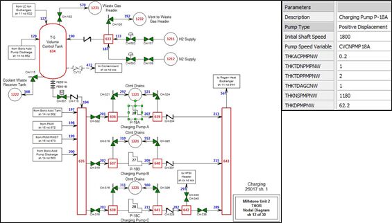
A recent development has been the introduction of the THOR 3-G models, which are developed and maintained using a graphical modeling environment. This has made the THOR models much easier to develop and maintain for end users. The THOR 3-G tools will be used to develop the Bruce 7 models. Through this tool the nodal diagrams are drawn, and all model components, volumes and flowpaths are defined. After the drawings are completed they are used to generate the model.
The THOR 3-G model builder generates:
THOR input interface file
Simulator database ‘ADD’ file for the THOR variables
Initialization file for the THOR constants
Initialization file for THOR variables to create initial condition
The drawings may then serve as the repository of all of the data used to develop the model. Changes to data or model constants are tracked through the drawings database, providing configuration control.
Drawings may be viewed live while the models are running to provide data for development and troubleshooting. Below is a typical THOR 3-G drawing with a component data definition menu.